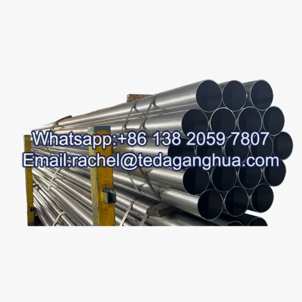
- Description
Description
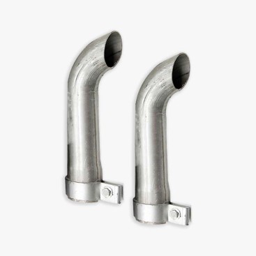
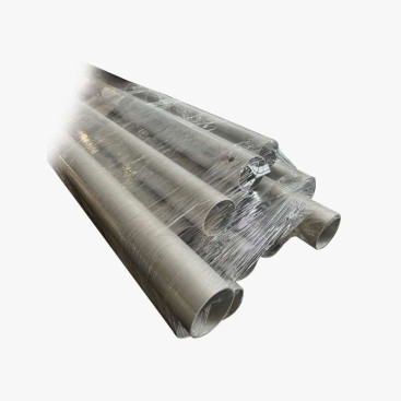
An aluminized exhaust stack should be specified as a complete exhaust assembly rather than as a single straight tube. A working system normally combines vertical or horizontal pipe sections, elbows, a rain cap, clamps, brackets, flanges and sealing components. The material must handle exhaust heat while the assembly must also control backpressure, thermal movement, vibration, rainwater and condensate. Aluminized steel is widely used for traditional diesel exhaust components because its aluminum-based surface provides a protective barrier and good resistance to acidic exhaust environments. Donaldson lists aluminized steel as a common exhaust material and gives a continuous-duty temperature limit of 538°C (1,000°F) for its exhaust applications. :contentReference[oaicite:0]{index=0}
Exhaust Stack System: From Pipe to Rain Cap
The system perspective changes the procurement question from “What tube size do I need?” to “How will every component work together after installation?” A typical vertical assembly can be divided into five functional groups.
| Component | Primary Function | Key Specification |
|---|---|---|
| Pipe sections | Carry exhaust gas and establish the main flow path | Diameter, wall thickness, length, material and coating |
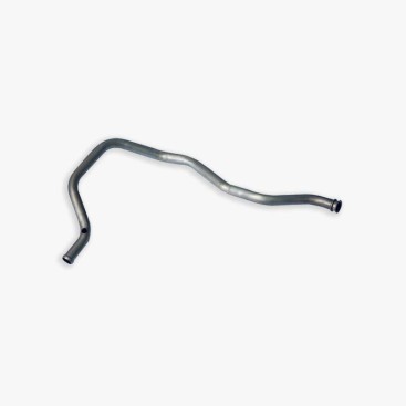
| Elbows | Change the direction of the exhaust route | Angle, centerline radius and connection size |
| Rain cap | Limit direct rain entry at the stack outlet | Outlet diameter, opening area and temperature suitability |
| Clamps / flanges | Join removable sections and maintain the seal | Joint geometry, bolt pattern, gasket and temperature rating |
| Brackets / hangers | Transfer pipe weight and lateral loads to the structure | Load capacity, spacing and thermal movement allowance |
Commercial exhaust catalogs similarly treat exhaust systems as groups of components rather than isolated tubes, including pipes, elbows, clamps and accessories. :contentReference[oaicite:1]{index=1}
Vertical Stack vs Horizontal Exhaust Layout
A vertical stack and a horizontal exhaust line can use the same basic tube material but have very different mechanical requirements. The vertical configuration concentrates the weight of upper sections into the support structure, while the horizontal configuration requires more attention to sagging, hanger spacing and drainage.
Vertical Layout
Typical concerns include self-weight, wind load, lateral stability, roof penetration, rain entry and thermal expansion along the height of the stack.
Priority: structural support + expansion + weather protection.
Horizontal Layout
Typical concerns include unsupported span, sagging, low points where condensate can accumulate, elbows and increased flow resistance.
Priority: hanger spacing + drainage + flow resistance.
Regardless of orientation, excessive restriction should be avoided. Exhaust-system backpressure is affected by tube diameter, length, elbows, contractions and outlet geometry; excessive backpressure can adversely affect engine performance. :contentReference[oaicite:2]{index=2}
Diameter Selection: Engine Displacement Is Only the Starting Point
Engine displacement can provide a useful first indication of exhaust-system scale, but it should not be used as the sole basis for selecting stack diameter. The actual exhaust flow rate, allowable backpressure, engine operating condition, turbocharger configuration and exhaust-system length all influence the required diameter.
| Selection Input | Why It Matters |
|---|---|
| Engine displacement | Useful for initial equipment classification but does not directly define exhaust flow. |
| Exhaust flow rate | Provides the direct basis for evaluating pipe capacity and velocity. |
| Maximum backpressure | Sets an upper limit on system resistance. |
| Pipe length | Longer runs increase friction losses. |
| Elbows and fittings | Each change of direction and restriction contributes additional pressure loss. |
| Operating temperature | Influences material selection, expansion and insulation requirements. |
Donaldson’s exhaust selection guidance specifically recommends determining exhaust flow and acceptable system backpressure from the engine manufacturer when sizing exhaust components. :contentReference[oaicite:3]{index=3}
Procurement rule: use engine displacement to establish the initial size range, then verify the final diameter against actual exhaust flow and allowable backpressure. Do not select a larger tube solely because “larger is always better”; system geometry and outlet velocity also matter.
Pipe and Fitting Material: Why Aluminized Steel Is Used
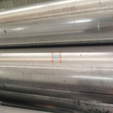
Aluminized steel combines a steel substrate with an aluminum-based protective surface. Cleveland-Cliffs lists both Aluminized Type 1 and Type 2 among its coated-steel products, while its tubular operations identify aluminized carbon and stainless products for exhaust-related markets. :contentReference[oaicite:4]{index=4}
For traditional diesel exhaust applications, the coating provides a practical barrier against the exhaust environment while maintaining the fabrication advantages of steel tubing. Donaldson describes aluminized steel as a preferred material for traditional diesel exhaust and notes its corrosion resistance to acidic diesel exhaust gases. :contentReference[oaicite:5]{index=5}
However, the complete system still depends on the weakest component. A coated straight pipe does not compensate for an unsuitable clamp, poorly protected weld, undersized bracket or rain cap that allows persistent water accumulation.
Sealing: Keep Exhaust Inside and Water Outside
Every joint should be evaluated for two different leakage mechanisms: hot exhaust leakage outward and rain or condensate leakage inward. A system can appear mechanically secure while still developing leaks because of thermal cycling or inadequate joint compression.
| Joint Area | Typical Risk | Preventive Measure |
|---|---|---|
| Pipe-to-pipe joint | Exhaust leakage after thermal cycling | Correct joint geometry and temperature-compatible sealing |
| Flanged joint | Gasket relaxation or uneven bolt loading | Correct gasket, flange flatness and tightening procedure |
| Rain-cap connection | Water entering the stack | Correct cap geometry and secure attachment |
| Fabricated joint | Local coating damage and corrosion initiation | Appropriate post-fabrication protection |
Thermal Expansion: The Stack Must Be Able to Move
A long exhaust stack changes length as it heats and cools. Rigidly fixing every section can transfer thermal movement into flanges, brackets, welds or connected equipment. A better assembly provides defined fixed points and controlled movement points.
Fixed support
Controls the position of the stack and transfers structural loads.
Guided support
Restrains excessive lateral movement while allowing the intended axial movement.
Expansion allowance
Prevents thermal growth from being transferred directly into rigid building or equipment connections.
The exact support arrangement depends on stack height, operating temperature, section length, building structure and connection design. It should therefore be engineered as part of the complete exhaust installation rather than selected independently from the pipe.
Rain Cap and Bracket Design
The rain cap has a simple purpose but operates in a harsh location: directly above the hot exhaust outlet and exposed to wind and precipitation. It should allow exhaust to discharge freely while limiting direct rain entry and maintaining adequate mechanical attachment.
Brackets perform the opposite task: they are primarily structural. A tall vertical stack should not rely on the roof penetration or engine connection to carry the entire assembly. Bracket spacing should be based on pipe weight, wind exposure, vibration and the allowable load of the supporting structure.
System arrangement example:
Engine outlet → flexible/isolating connection where required → horizontal pipe → elbow → vertical stack → fixed support → guided brackets → roof sleeve → flashing → upper stack section → rain cap.
Common Failure Points and Prevention
| Failure Point | Typical Cause | Prevention |
|---|---|---|
| Exhaust leakage | Poor joint alignment or inadequate sealing | Control joint fit-up and use temperature-appropriate sealing components |
| Condensation corrosion | Cold sections and trapped moisture | Consider insulation, drainage and operating conditions |
| Bracket cracking | Excessive thermal or vibration load | Provide correct support spacing and movement allowance |
| Stack deformation | Insufficient wall thickness or excessive unsupported length | Verify structural loading and section design |
| High backpressure | Undersized diameter, excessive elbows or restrictions | Size from exhaust flow and allowable backpressure |
| Rainwater entry | Poor rain-cap geometry or installation | Use a suitable cap and maintain proper outlet orientation |
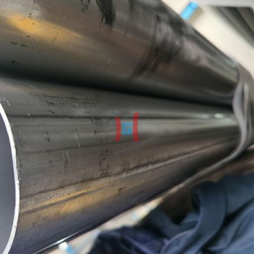
| Local coating damage | Welding, cutting, grinding or rough handling | Inspect fabricated areas and apply the specified repair protection |
Procurement Checklist for a Complete Exhaust Stack
For a system quotation, provide more information than the pipe diameter. A useful RFQ should include:
- Engine type and displacement
- Exhaust flow rate or engine manufacturer’s recommended exhaust diameter
- Maximum allowable backpressure
- Pipe outside diameter and wall thickness
- Total stack height and individual section lengths
- Number and angle of elbows
- Rain-cap type
- Flange, clamp or welded connection method
- Bracket and hanger locations
- Operating temperature and duty cycle
- Insulation requirements
- Roof penetration and flashing arrangement
- Required coating and base-steel specification
Teda Ganghua Supply Support
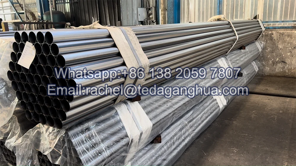
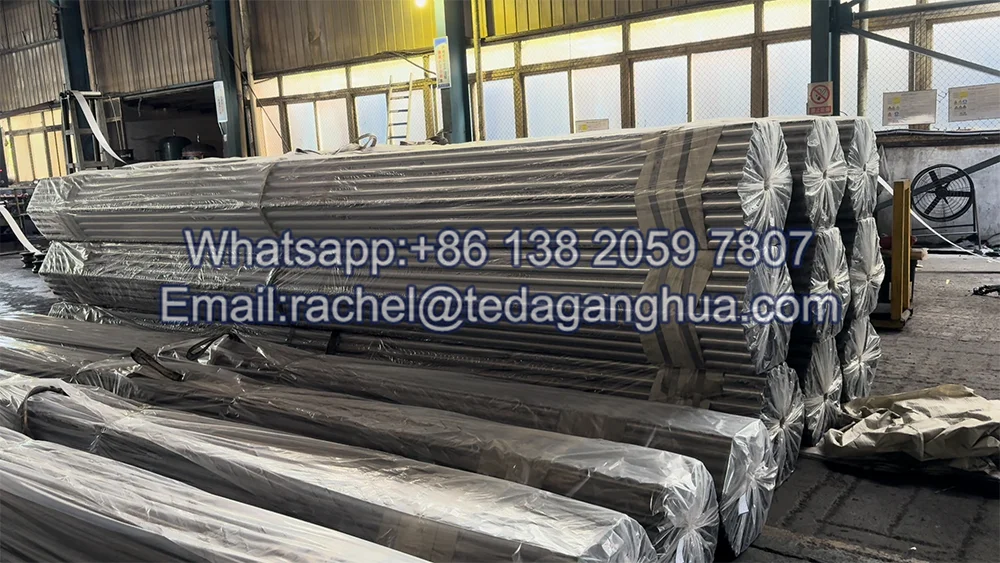
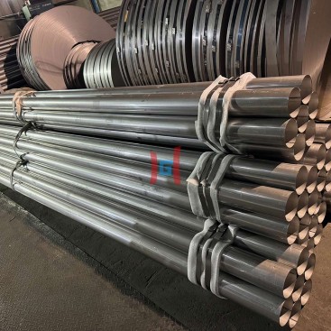
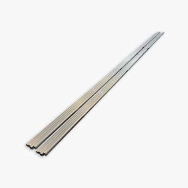
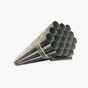
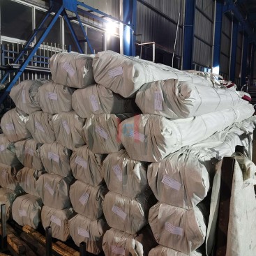
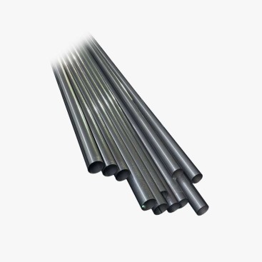
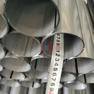
Teda Ganghua can support projects requiring aluminized steel tubes for exhaust assemblies, including specified outside diameter, wall thickness, cut length and coating requirements. For a complete stack quotation, buyers can submit the engine information, pipe dimensions, total height, section lengths, elbow configuration, connection method and required brackets or other fabricated components.
This system-based specification helps separate the material supply from the installation design while keeping the two coordinated. The tube, fittings, joints and supports should be reviewed as one exhaust path so that thermal movement, backpressure, condensate and structural loads are addressed before production.
FAQ
1. Is an exhaust stack just a long piece of exhaust pipe?
No. A stack is normally a complete assembly that can include pipe sections, elbows, clamps or flanges, brackets, a rain cap and sometimes insulation and a roof penetration assembly. The interaction between these components is important for long vertical runs.
2. Should engine displacement alone determine stack diameter?
No. Displacement is useful for initial sizing, but exhaust flow and allowable backpressure should be verified from the engine manufacturer’s data. Pipe length, elbows and other restrictions also affect pressure loss. :contentReference[oaicite:6]{index=6}
3. Why does a vertical stack need brackets?
Brackets transfer the weight and lateral loads of the stack to the supporting structure. They also help control movement caused by wind, vibration and thermal expansion.
4. What is the purpose of a rain cap?
A rain cap helps reduce direct precipitation entering the open stack while maintaining an outlet path for exhaust gas. Its geometry should be selected together with the pipe diameter and operating conditions.
5. Why should thermal expansion be considered in the whole system?
Heating causes the stack to expand and cooling causes it to contract. If every support and connection is rigid, that movement can load brackets, welds, flanges or connected equipment. Fixed and guided supports should therefore be coordinated with the expected thermal movement.