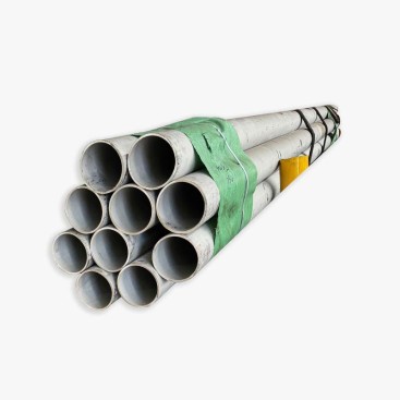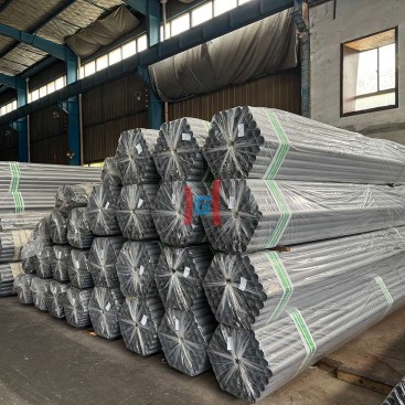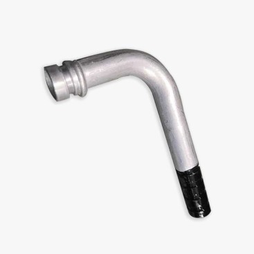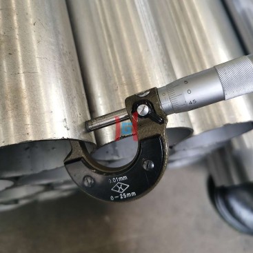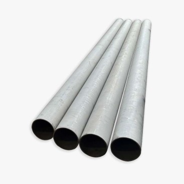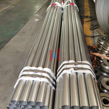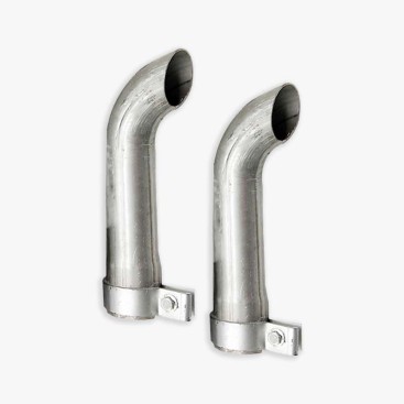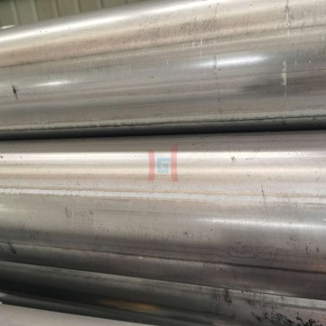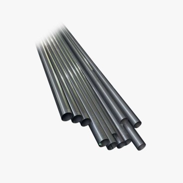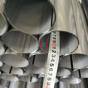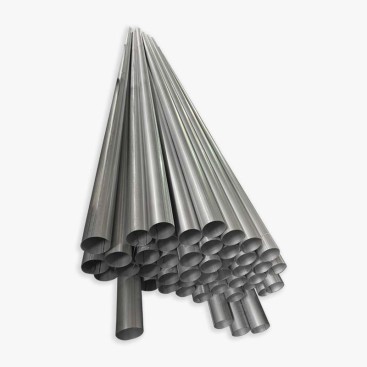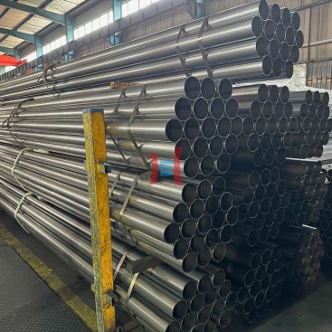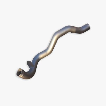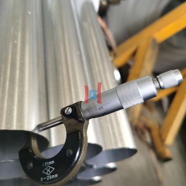
Tubo de escape aluminizado para semi-caminhão
- Descrição
Descrição
A semi-truck exhaust system becomes mechanically demanding when a long pipe run combines large diameter, high exhaust flow, vibração, and repeated thermal cycling. For runs longer than 3 eu, the pipe should be treated as a supported thermal structure rather than simply a long piece of tubing. Diameter selection, hanger layout, expansion compensation, aftertreatment interfaces, and final outlet geometry all need to be considered together. Commercial exhaust systems commonly use aluminized steel tubing, flexible sections, connectors, clamps, elbows, hangers, and brackets as an integrated system.
Why Semi-Truck Long Exhaust Runs Need a Different Design
On a semi truck, the exhaust route may extend from the aftertreatment outlet toward a vertical stack or rear discharge while the chassis experiences road shock and relative movement. A long rigid section increases its own weight and thermal growth, while a large diameter increases the cross-sectional area and therefore the structural load carried by each support. Exhaust supports must hold the pipe securely while still allowing thermal expansion and vibration movement.
| Design factor | Long-run concern | Procurement implication |
|---|---|---|
| Run length | More dead weight and thermal growth | Confirm cut length, support points, and expansion allowance |
| Diâmetro | Higher flow area but greater pipe mass | Specify actual ID/OD and wall thickness |
| Vibration | Engine and road movement can fatigue joints | Use appropriate flex sections and isolated hangers |
| Temperatura | Repeated heating and cooling changes pipe length | Locate expansion compensation according to the system layout |
| Aftertreatment | Connection temperature and backpressure affect system operation | Match the OEM interface and emissions-system requirements |
Long Runs Over 3 eu: Support the Pipe Without Locking It
A pipe longer than 3 m should not simply be fixed rigidly at both ends. The mounting system needs to control sagging and lateral movement while providing a defined direction for thermal expansion. Heavy-duty exhaust guidance emphasizes secure support with allowance for thermal expansion and contraction; added hangers should not bind the exhaust as it grows when heated.
There is no universal hanger spacing that applies to every semi-truck configuration. The correct interval depends on pipe diameter, espessura da parede, unsupported weight, bends, connection locations, chassis geometry, vibration level, and OEM requirements. As a procurement starting point, a long straight section can be divided into repeated support spans, with closer support near heavy components, bends, joints, and changes in direction. Some engine exhaust installation manuals specify approximately 0.6–0.9 m hanger intervals for their particular systems, illustrating why spacing should be treated as application-specific rather than as a universal rule.
| Pipe location | Support approach | Reason |
|---|---|---|
| Near heavy connector or muffler | Additional support as required | Reduce concentrated load on the adjacent pipe |
| Long straight section | Regular hanger spacing based on engineering calculation | Control sag and vibration |
| Near bend or direction change | Closer support when necessary | Limit bending movement and joint loading |
| Expansion/flex section | Guide movement rather than rigidly restrain it | Allow designed axial or angular movement |
5–8 Inch Diameter: Flow Area vs Structural Load
Large exhaust diameters are selected to provide the required flow area and help control exhaust restriction. Increasing diameter can increase available flow area, but it also increases the pipe’s physical envelope, peso, and sensitivity to unsupported spans. The correct diameter therefore should come from the engine and exhaust-system design rather than from a generic “larger is always better” rule. Smooth bends and unrestricted routing are important because sharp edges or poorly designed bends can increase exhaust backpressure.
| Nominal diameter | Typical procurement focus | Design checkpoint |
|---|---|---|
| 5 em | Common large-diameter commercial exhaust configuration | Confirm ID/OD, connector type and available clearance |
| 6 em | Higher flow-area requirement | Check weight, hanger capacity and routing envelope |
| 7 em | Specialized high-flow configuration | Verify OEM/system diameter before fabrication |
| 8 em | Very large flow-area configuration | Review structural support and thermal movement carefully |
Commercial exhaust hardware is available across large diameters, incluindo 5- and 6-inch components, while connectors, reducers, spouts, hangers, and brackets are also available as matched exhaust-system hardware.
Thermal Expansion: Put the Expansion Point in the Right Place
Long exhaust pipes expand as their temperature rises. If both ends are restrained and intermediate supports prevent movement, thermal growth can transfer excessive force into flanges, joints, colchetes, or engine connections. The expansion element should therefore be positioned according to the fixed-point and guide layout rather than simply inserted at the middle of a long pipe. Exhaust-system engineering references specifically require flexible expansion elements and support arrangements that accommodate thermal growth and vibration.
For a semi-truck layout, the practical sequence is usually to establish the engine/aftertreatment connection, identify the fixed support or controlled anchor point, define the direction of thermal movement, and then position the flexible or expansion section where it can absorb the expected movement without imposing excessive load on the upstream equipment.
Important: Do not use a flexible section as a substitute for correct routing. Commercial flex tubing is intended to damp vibration and movement, and installation guidance recommends keeping it in its designed “natural lie” rather than forcing it fully compressed or extended.
Interface With DPF and SCR Aftertreatment
The section immediately connected to a diesel aftertreatment system should be specified differently from a downstream long tailpipe. Exhaust temperature at the aftertreatment inlet is important to the operation and regeneration of diesel particulate filters, so insulation, material, routing, and connection geometry near the aftertreatment device must follow the engine or vehicle manufacturer’s requirements. One engine installation manual, for example, specifies insulation between the turbocharger and aftertreatment inlet to preserve exhaust temperature for DOC and DPF operation.
| Interface zone | Primary concern | Specification check |
|---|---|---|
| Turbocharger to aftertreatment | Temperature retention and vibration | OEM material, insulation and flex requirements |
| DPF/DOC/SCR outlet | Connection geometry and backpressure | Flange, clamp, gasket, diameter and OEM interface |
| Long downstream run | Thermal growth and structural support | Comprimento, parede, hanger layout and expansion allowance |
| Stack/outlet | Clearance, vibration and weather exposure | Outlet style, colchetes, rain protection and final height |
For this reason, a procurement specification should not simply state “aluminized exhaust pipe.” It should identify where the pipe sits relative to the DPF/SCR system and whether the vehicle OEM permits aluminized construction in that specific section.
Custom Lengths for Semi-Truck Production
Long-run projects benefit from supplying cut-to-length sections instead of forcing installers to join unnecessary short pieces in the field. A commercial exhaust supplier may offer different lengths and diameters, while specialized flexible sections can also be supplied in multiple cut lengths.
| Order item | Information to provide |
|---|---|
| Straight pipe | OD or ID, espessura da parede, cut length, quantidade |
| Long section >3 eu | Overall length, support locations, transport length limit |
| Large diameter | 5–8 in target diameter, actual connection dimensions, clearance |
| End preparation | Plain end, expanded end, reduced end, flange or clamp connection |
| Batch order | Monthly quantity, packaging method, lot identification and inspection documents |
Teda Ganghua Custom Supply for Long Truck Exhaust Runs
For fleet replacement programs, exhaust-system fabricators, and truck-parts distributors, Teda Ganghua can organize tube supply around the actual vehicle specification rather than treating every order as a standard short pipe. The purchasing package can be built around diameter, espessura da parede, cut length, exigência de revestimento, end preparation, inspection documentation, and batch quantity. For large recurring orders, standardized dimensions can also simplify repeat purchasing and production planning.
When the required product is a semi truck aluminized exhaust pipe, provide the target diameter, espessura da parede, comprimento individual, total quantity, connection type, and whether the section is upstream or downstream of the DPF/SCR system. This allows the tube specification to be checked before production rather than after installation.
Semi-Truck Long-Run Procurement Checklist
Confirm 5–8 in nominal size and whether the drawing controls ID or OD.
Specify nominal wall thickness and required tolerance.
Identify every straight section and custom cut length.
Provide hanger and fixed-point locations where available.
Identify flex, bellows, or other thermal-movement provisions.
State DPF/SCR position and OEM interface requirements.
FAQs
1. Can a long semi-truck exhaust section be made longer than 3 eu?
Sim, but the longer the section becomes, the more important support, transport handling, thermal expansion, vibration isolation, and installation geometry become. Long sections should be designed around the actual vehicle routing rather than selected only by nominal length.
2. Is 8-inch exhaust pipe automatically better than 5-inch pipe?
Não. A larger diameter provides greater flow area, but the required diameter depends on engine output, exhaust-system design, allowable backpressure, embalagem, and OEM specifications. Oversizing should not replace a proper flow and routing calculation.
3. Where should the expansion section be installed?
Its location depends on the fixed-point and guide arrangement, temperature distribution, engine movement, and the location of the aftertreatment equipment. The expansion element should be positioned to absorb the calculated movement without transferring excessive loads to the engine or aftertreatment connections. :referência de conteúdo[ovelha:10]{index=10}
4. A tubulação aluminizada pode ser conectada diretamente a um sistema DPF ou SCR?
Somente quando o projeto específico do motor ou veículo permitir que o material e o arranjo de conexão. A seção de alta temperatura próxima ao motor e ao equipamento de pós-tratamento pode ter diferentes requisitos de material e isolamento do tubo de escape a jusante, então a especificação OEM deve controlar.
5. Quais informações são necessárias para um pedido em massa com tamanho personalizado?
No mínimo, fornecer diâmetro, Referência de ID ou OD, espessura da parede, comprimento de corte individual, total quantity, exigência de material/revestimento, end preparation, connection type, e a posição do tubo em relação ao sistema DPF/SCR. Um desenho de rota ou montagem de amostra é útil quando múltiplas dobras ou pontos de conexão estão envolvidos.