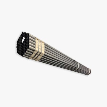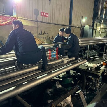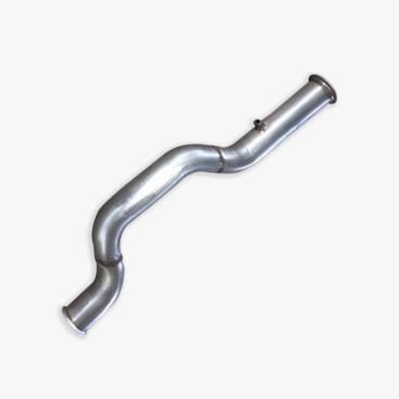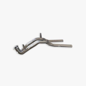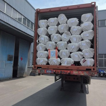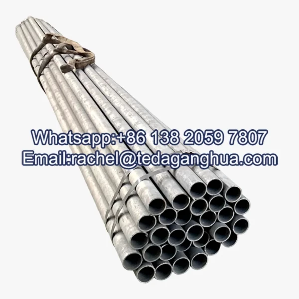
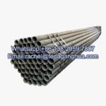
- Description
Description
A 1.2 mm wall is designed for applications where low weight, material efficiency, and heat transfer performance are important. However, reducing wall thickness also narrows the process window for tube forming, welding, coating protection, and downstream fabrication. For aluminized steel tubing, the challenge is not simply achieving the specified nominal thickness. The finished tube must maintain dimensional consistency, reliable weld integrity, and coating adhesion through bending, flaring, assembly, and thermal cycling.
Before selecting this wall thickness, procurement and engineering teams should evaluate the operating temperature, internal pressure, mechanical loading, corrosion exposure, and manufacturing tolerances. A thin-wall specification can be effective in exhaust components, heat-exchange passages, and ventilation systems, but it should not be treated as a universal replacement for thicker tubing.
1. Where a 1.2 mm Wall Fits in Tube Design
At 1.2 mm, the tube wall prioritizes material reduction and efficient thermal response. Compared with a thicker tube of otherwise similar dimensions, it generally reduces steel consumption and component mass. In suitable heat-transfer applications, a thinner metal wall can also reduce the wall’s contribution to thermal resistance, although actual performance depends on the complete heat-transfer system, including fluid flow, surface area, deposits, and temperature gradients.
Potential Advantages
- Lower component weight and reduced material consumption.
- Efficient heat transfer where wall conduction is a significant part of total thermal resistance.
- Greater flexibility in designing compact exhaust, heating, and ventilation assemblies.
- Potentially reduced forming loads, depending on tube diameter, material strength, and tooling geometry.
These advantages depend on application-specific validation. A thinner wall also reduces the available allowance for corrosion, local deformation, handling damage, and manufacturing variation. Designers should therefore confirm the minimum permitted finished-wall thickness rather than relying on the nominal dimension alone.
2. Forming and Welding Constraints
Weld Burn-Through and Heat Input
Thin-wall tube welding requires careful control of current, voltage, travel speed, arc stability, joint fit-up, and shielding conditions. Excessive localized heat can cause burn-through, undercut, excessive penetration, or distortion. Insufficient heat or unstable process conditions can produce incomplete fusion and inconsistent weld profiles.
There is no single welding speed or heat-input value suitable for every 1.2 mm tube. The acceptable process window depends on the welding method, tube diameter, steel chemistry, joint design, equipment, and production rate. A qualified procedure should establish a stable combination of parameters using representative production material.
Weld Seam Profile and Internal Burrs
For welded tubing, internal weld projections and burrs can restrict flow, create local turbulence, collect deposits, and interfere with insertion or assembly. Excessive external weld reinforcement can also affect fit-up and finishing. Where internal smoothness is important, the order specification should define whether internal bead control, bead removal, or a maximum allowable projection is required.
Inspection should cover more than the visible external seam. Depending on the application, suitable checks may include visual examination, dimensional measurement, sectioned samples, leak testing, or other qualified weld-integrity tests. The inspection method must match the consequences of a weld defect.
Bending, Flaring, and Local Deformation
Thin-wall tubing is more susceptible to ovality, wrinkling, local flattening, and buckling during forming. Tight bend radii and aggressive expansion can concentrate strain at the outer surface or at the weld seam. Tooling clearance, mandrel support, lubrication, material condition, and the relationship between tube diameter and wall thickness all influence the result.
Trial forming should use the intended production geometry. If the tube will be flared or expanded, verify the finished dimensions and inspect the formed region for cracks, wrinkles, coating damage, and excessive thinning.
3. How Aluminized Coating Behaves on Thin Walls
An aluminum-silicon coating provides oxidation protection for suitable steel components exposed to elevated temperatures. On a thin substrate, however, coating quality and forming damage require particular attention. The coating does not compensate for inadequate structural wall thickness, and its presence does not automatically establish suitability for a specific operating temperature or corrosive environment.
Three Coating Risks to Check
- Relative coating contribution: The coating may represent a more noticeable proportion of the total cross-section as the substrate becomes thinner. Specify coating mass or thickness separately from the steel base thickness.
- Cracking during forming: Bending, expansion, and flaring impose strain on the coated surface. Tight radii and severe deformation can produce coating cracks or local separation.
- Damage during handling and welding: Scratches, clamping marks, weld heat, and post-weld finishing may compromise local protection. Evaluate the affected region according to the component’s service conditions.
Acceptance criteria should distinguish cosmetic discoloration from actual coating damage. Minor appearance changes do not necessarily indicate failure, while exposed substrate, flaking, or separation in a critical service area may require corrective action. Where post-forming or post-weld protection is necessary, use a repair method approved for the intended temperature and environment.
4. Suitable and Unsuitable Applications
| Application | Suitability and Conditions |
|---|---|
| Exhaust tailpipes and muffler inner tubes | Potentially suitable where temperature, vibration, condensation, thermal cycling, and exhaust chemistry are within the material’s qualified limits. |
| Heat-exchange and heater tubes | Suitable for evaluation when heat transfer is important and pressure, corrosion allowance, and thermal fatigue requirements are satisfied. |
| Drying and ventilation ducts | Potentially suitable for lightweight air-handling paths with limited mechanical loading and compatible operating conditions. |
| Pressurized piping | Not suitable by default. Pressure design, material strength, weld efficiency, temperature, cyclic loading, and applicable codes must be evaluated. |
| Load-bearing structures | Not a default choice where buckling resistance, impact resistance, or sustained structural loads govern the design. |
| Severe abrasive service | Generally requires a dedicated wear assessment because the thin substrate provides limited material allowance for wall loss. |
These classifications are preliminary design guidance, not a substitute for engineering approval. Actual suitability depends on tube diameter, load cases, operating conditions, material properties, fabrication quality, and the relevant design code.
5. Wall Thickness, Key Risks, and Inspection Actions
For thin-wall purchasing, inspection should be linked directly to the failure mode. The following table provides a practical framework for incoming inspection, production qualification, and supplier discussions.
| Control Item | Main Risk | Inspection Action | Acceptance Basis |
|---|---|---|---|
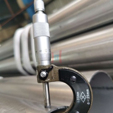
| Base wall thickness | Insufficient strength or local thinning | Measure multiple positions and sample locations; use a calibrated method suitable for the tube geometry. | Purchase specification and applicable dimensional tolerance |
| Weld seam | Burn-through, incomplete fusion, excessive bead | Visual inspection plus application-appropriate weld or leak testing | Qualified welding procedure and agreed defect limits |
| Internal burr or bead | Flow restriction or assembly interference | Inspect the internal profile using suitable visual, borescope, or sectioned-sample methods. | Specified maximum projection or functional requirement |
| Tube diameter and ovality | Poor fit-up and deformation | Measure outside diameter in multiple directions and verify straightness where required. | Drawing tolerances and assembly requirements |
| Aluminum-silicon coating | Uneven coverage, flaking, or exposed substrate | Check coating designation, agreed coating mass or thickness, surface condition, and test results where specified. | Coating specification and service-related acceptance criteria |
| Bend or flare region | Cracking, wrinkles, coating separation | Form representative samples and inspect dimensions, surface integrity, and remaining wall where necessary. | Approved forming trial and component drawing |
| Material traceability | Unverified grade or coating condition | Review the material certificate, batch identification, and inspection records. | Purchase order and required documentation |
Important measurement note: A nominal 1.2 mm specification does not automatically mean every point on the finished tube must measure exactly 1.2 mm. Confirm whether the stated value refers to the steel substrate or the coated product, how thickness is measured, and which negative tolerance applies. Coating mass, substrate thickness, and finished-tube dimensions should not be treated as interchangeable quantities.
6. Procurement Checklist for Thin-Wall Tubing
Before issuing a purchase order, align the technical specification with the intended manufacturing process. A clear specification reduces disputes over nominal dimensions, coating condition, weld quality, and application suitability.
- Confirm the steel grade, applicable product standard, and delivery condition.
- Define whether 1.2 mm refers to the steel base thickness or the coated product thickness.
- Specify outside diameter, length, dimensional tolerances, straightness, and ovality limits.
- State the coating designation and required coating mass or thickness, including the relevant measurement basis.
- Identify weld-seam requirements, internal bead limits, and leak or integrity tests where necessary.
- Describe subsequent bending, flaring, cutting, welding, and assembly operations.
- Provide service temperature, pressure, vibration, corrosion exposure, and expected operating life.
- Agree on sampling frequency, inspection records, material certificates, and nonconformance handling.
For projects requiring repeatable fabrication, ask the supplier to evaluate sample tubes using the actual bend radius, flare geometry, joining method, and inspection criteria. A successful trial on representative material provides stronger evidence of process suitability than nominal thickness alone.
7. Sourcing Support from Teda Ganghua
Teda Ganghua supports industrial buyers evaluating coated steel tubing and related steel products by clarifying dimensions, material requirements, coating specifications, and inspection expectations before order confirmation. For thin-wall applications, this specification-first approach helps procurement teams align the requested product with downstream forming, welding, and service conditions.
When requesting a quotation, provide the target wall thickness, outside diameter, required length, coating designation, application, annual or trial quantity, and any relevant drawings or test requirements. Buyers can review the available aluminized steel tubes product information and submit their technical requirements for evaluation. Final supply suitability should be confirmed against the agreed specification and intended operating conditions.
Frequently Asked Questions
1. Is a 1.2 mm wall suitable for exhaust tubing?
It can be suitable for selected exhaust components when temperature, vibration, thermal cycling, corrosion exposure, and mechanical loading remain within the design limits. The complete assembly should be validated under representative service conditions.
2. Why is thin-wall tube welding more difficult?
The smaller amount of base metal makes localized overheating more consequential. Burn-through, distortion, inconsistent penetration, and excessive weld reinforcement can occur if joint fit-up and welding parameters are not properly controlled.
3. Does aluminized coating increase the specified wall thickness?
The coating contributes to the finished product’s overall dimensions, but the amount depends on the coating system and measurement method. Purchase documents should separately identify the substrate thickness, coating requirement, and dimensional acceptance basis.
4. Can a 1.2 mm tube be bent or flared without coating damage?
It may be possible with suitable tooling, material condition, bend radius, and forming parameters. Representative trials should verify dimensional stability, surface integrity, and any coating acceptance requirements before full production.
5. What information is essential when ordering thin-wall coated tubing?
Specify the material grade and standard, substrate wall thickness, outside diameter, length, coating designation, dimensional tolerances, weld requirements, operating conditions, inspection criteria, and documentation needs. Include drawings when the tube requires specialized forming or assembly.