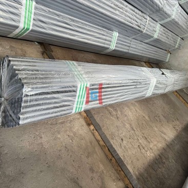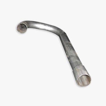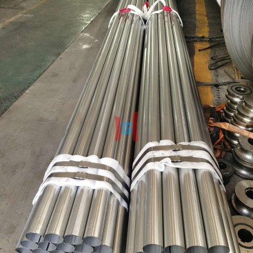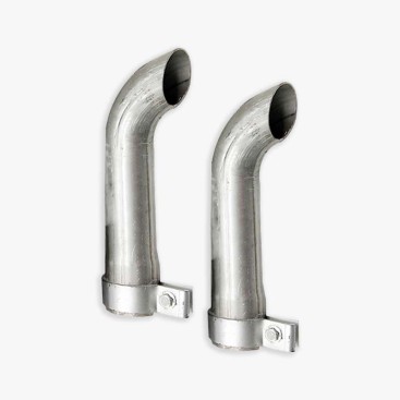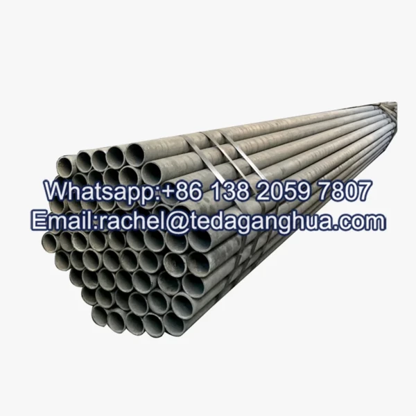
- Description
Description
A 2.5 mm wall offers a practical middle ground between lightweight tubing and heavier-duty steel tube construction. Compared with thinner-wall alternatives, it generally provides greater section stiffness, more resistance to local deformation, and a wider processing window for many bending, welding, and forming operations. The trade-off is increased material consumption, component weight, and potentially higher transportation and fabrication costs.
For aluminized steel tube applications, selecting a 2.5 mm wall should involve more than comparing nominal thicknesses. Tube diameter, steel grade, coating specification, operating temperature, loading conditions, and manufacturing tolerances all influence performance. Procurement teams should also consider whether existing brackets, clamps, connectors, and forming tools can accommodate the revised dimensions.
1. Why Choose a 2.5 mm Wall?
A medium-wall tube is often selected when a thin-wall design does not provide enough rigidity or fabrication allowance, but a substantially thicker section would add unnecessary mass. The actual benefit depends on the tube’s outside diameter, material properties, and loading conditions.
Greater Rigidity
A thicker wall generally improves resistance to local denting and ovalization, helping maintain tube geometry during handling and assembly.
More Processing Allowance
The additional material can provide greater tolerance for certain forming operations, provided the tooling and process are correctly specified.
Higher Material Demand
More steel per metre increases component mass and may affect material cost, freight, installation effort, and supporting hardware.
Wall thickness alone does not determine structural capacity. A large-diameter tube with a 2.5 mm wall may behave differently from a small-diameter tube of the same thickness. Designers should evaluate the complete section geometry and the applicable load cases before treating the thicker option as a direct strength upgrade.
2. How Wall Thickness Affects Weight and Cost
For a tube with a fixed outside diameter, increasing wall thickness increases the cross-sectional area of steel. The relationship is nonlinear because the inside diameter decreases as the wall becomes thicker. Consequently, weight per metre should be calculated from the actual dimensions rather than estimated by applying the percentage increase in wall thickness directly to the finished tube weight.
Steel Tube Weight Formula
Cross-sectional area:
A = π × t × (D − t)
Theoretical mass per metre:
m = ρ × π × t × (D − t) × 10⁻⁶
Where D is the outside diameter in millimetres, t is the steel substrate wall thickness in millimetres, and ρ is the steel density in kg/m³. The formula gives the theoretical mass of the steel substrate per metre when the dimensions are uniform.
For preliminary calculations, a steel density of approximately 7,850 kg/m³ is commonly used. Actual product mass can differ because of dimensional tolerances, steel composition, coating contribution, weld geometry, and manufacturing variation. Confirm the calculation basis with the supplier, particularly when the specified wall thickness refers to the coated product rather than the steel substrate.
| Outside Diameter | Wall Thickness | Approx. Steel Mass per Metre |
|---|---|---|
| 50 mm | 1.2 mm | 1.44 kg/m |
| 50 mm | 2.5 mm | 2.92 kg/m |
| 76.1 mm | 1.2 mm | 2.23 kg/m |
| 76.1 mm | 2.5 mm | 3.62 kg/m |
Note: Values are illustrative theoretical calculations for a steel density of 7,850 kg/m³. They exclude coating mass and manufacturing tolerances and are not supplier-certified weights.
These examples show why the diameter must be included in any weight comparison. At a fixed outside diameter, a change from 1.2 mm to 2.5 mm produces a substantial increase in theoretical steel mass. However, the corresponding cost change cannot be assumed to be identical to the weight increase because processing, cutting, coating, yield, packaging, and logistics may also contribute to the final quotation.
3. Bending, Welding, and Forming Performance
Bending Radius and Dimensional Stability
A 2.5 mm wall can resist local collapse better than a thinner wall under comparable conditions. This may improve dimensional stability during bending and reduce the tendency toward ovalization or wrinkling. Nevertheless, a thicker wall is not automatically suitable for a tighter bend radius. The required bending force increases, and the outer surface still experiences tensile strain while the inner surface is compressed.
Minimum bend radius should be established using the tube diameter, material grade, wall thickness, bending method, tooling, and permitted deformation. Mandrel support or other internal support may still be required for tight-radius bends. Trial bending should confirm ovality, surface condition, springback, and dimensional compliance.
Welding Tolerance and Heat Input
Compared with very thin-wall tubing, a 2.5 mm wall generally provides a wider practical window for controlling localized heat during welding. The risk of immediate burn-through can be lower when other variables are comparable. However, excessive heat input can still cause distortion, undercut, excessive penetration, or deterioration of the coating near the weld.
Welding parameters should be qualified for the actual material, joint design, welding process, and production speed. If the tube will be used in a hot-gas or exhaust system, evaluate the weld and heat-affected region under the relevant thermal and corrosion conditions. Do not assume that a thicker wall eliminates the need for weld inspection or post-weld protection.
Flaring and Roll Forming
A medium-wall section can offer better resistance to local deformation during flaring and roll forming, especially when the tooling is designed for the selected dimensions. However, thicker material may require greater forming force and can increase strain at edges, transition zones, and weld seams.
Confirm the tooling diameter, die clearance, expansion ratio, edge preparation, and lubrication requirements. Representative samples should be inspected for cracking, wrinkles, dimensional deviation, and local wall thinning before production quantities are approved.
4. Coating Behavior on a 2.5 mm Substrate
Aluminum-silicon-coated steel is used in applications where oxidation resistance and elevated-temperature performance are important. A thicker steel substrate can provide a more substantial structural section beneath the coating, but it does not automatically produce better coating adhesion or eliminate coating cracks.
Coating performance depends on the coating process, surface condition, coating specification, material condition, and subsequent fabrication. During bending, flaring, or roll forming, the coated surface remains subject to strain. The actual risk of cracking or separation depends on the coating system and forming severity rather than substrate thickness alone.
Coating Inspection Priorities
- Verify the coating designation and agreed coating mass or thickness independently of the steel base thickness.
- Inspect cut edges, weld zones, bends, and flared ends for exposed substrate or unacceptable coating separation.
- Confirm whether post-weld or post-forming protection is required by the application specification.
- Evaluate high-temperature oxidation resistance against actual operating temperature, atmosphere, thermal cycling, and expected service life.
For furnace tubes, exhaust components, and hot-gas ducts, service temperature alone is not sufficient to establish suitability. Gas chemistry, condensation during shutdown, thermal fatigue, mechanical loading, and local hot spots can all influence service life. The coating specification and substrate grade should therefore be selected as a complete material system.
5. Typical Applications for 2.5 mm Wall Tubing
| Application | Key Design Considerations |
|---|---|
| Exhaust manifolds and intermediate exhaust pipes | Thermal cycling, vibration, weld integrity, oxidation, thermal expansion, and exhaust chemistry. |
| Brackets and structural posts | Buckling resistance, connection geometry, eccentric loads, corrosion allowance, and applicable structural requirements. |
| Furnace and flue-gas ducts | Maximum metal temperature, gas composition, thermal movement, support spacing, and oxidation resistance. |
| Rigid frames and equipment supports | Section stiffness, local deformation, joint design, installation loads, and fatigue exposure. |
| Industrial air and heating systems | Airflow requirements, operating temperature, condensation, mounting loads, and dimensional stability. |
These applications are potential uses rather than blanket approvals. A 2.5 mm wall does not, by itself, qualify a tube for pressure service, structural certification, or a specific furnace temperature. The material standard, design calculations, testing, and applicable regulatory requirements must support the final selection.
6. Replacing Thin-Wall Tubing with a 2.5 mm Wall
Replacing a thinner tube with a 2.5 mm alternative may improve rigidity and resistance to handling damage, but the change affects the entire assembly. The outside diameter may remain constant while the inside diameter decreases. If the outside diameter changes as well, connector fit, mounting dimensions, and system performance may also be affected.
| Component or Parameter | Potential Effect of the Change | Required Review |
|---|---|---|
| Inside diameter | Reduced flow area if outside diameter is unchanged | Check flow, pressure drop, and clearance. |
| Clamps and connectors | Different insertion depth, grip, or interface geometry | Verify dimensions and joint compatibility. |
| Brackets and supports | Higher dead load and changed local contact conditions | Recheck load capacity, spacing, and fasteners. |
| Bending and forming tools | Higher forming force and potentially different springback | Run a tooling and process trial. |
| Weld procedure | Changed heat distribution and joint preparation requirements | Review and qualify the welding parameters. |
| Cost and logistics | Greater mass per metre and potentially higher freight or handling demand | Recalculate total installed cost and shipment weight. |
For a replacement project, compare the existing and proposed tubes using the same outside-diameter basis, material density, coating definition, and length. Then validate connections, fixtures, forming processes, and operating performance. A wall-thickness upgrade should be treated as an engineering change, not simply a purchasing substitution.
7. Procurement Checklist and Supplier Coordination
Before ordering medium-wall coated tubing, establish a common specification between engineering, purchasing, manufacturing, and the supplier. This reduces the risk of receiving material that meets a nominal thickness requirement but does not fit the assembly or service conditions.
- Specify steel grade, applicable product standard, delivery condition, and substrate thickness.
- Confirm outside diameter, length, tolerances, straightness, and ovality.
- Define the coating type and acceptance criteria for coating mass, thickness, and surface condition.
- Identify welding, bending, flaring, roll-forming, and post-processing requirements.
- Provide operating temperature, loading conditions, fluid or gas exposure, and expected service life.
- Request the required material certificates, batch traceability, and inspection documentation.
- Confirm packaging, handling, and delivery-length requirements to avoid damage and unnecessary fabrication work.
Teda Ganghua works with industrial buyers evaluating coated steel tube requirements, including dimensions, material specifications, coating conditions, and inspection documentation. For applications moving from thin-wall to medium-wall designs, clear technical communication helps align the product specification with the customer’s forming equipment, joining method, and installation requirements.
Buyers can review aluminized steel tubes and submit their target diameter, 2.5 mm wall requirement, coating specification, intended application, quantity, and drawings for technical review. Final product suitability should be confirmed against the approved specification and actual operating conditions.
Frequently Asked Questions
1. Is a 2.5 mm wall stronger than a 1.2 mm wall?
For the same outside diameter and comparable material, a 2.5 mm wall generally provides a larger steel cross-section and greater resistance to local deformation. Actual load capacity still depends on geometry, material properties, loading direction, connections, and design requirements.
2. How much heavier is a 2.5 mm tube?
The increase depends on outside diameter and steel density. Calculate theoretical mass per metre using the tube’s cross-sectional area, then account separately for coating mass and manufacturing tolerances. Supplier weight tables can be used to verify the order basis.
3. Is a thicker wall easier to bend and weld?
It can be less susceptible to local collapse and burn-through than a much thinner wall under comparable conditions. However, bending force and welding heat requirements change with thickness, so tooling and process parameters must be adjusted and qualified.
4. Does a 2.5 mm substrate prevent aluminized coating cracks?
No. Coating integrity depends on the coating system, surface condition, material properties, and forming strain. Bend radius, flare geometry, and forming method should be validated using representative coated samples.
5. Can a 2.5 mm tube directly replace an existing thin-wall tube?
Not without checking compatibility. Review the inside diameter, flow area, connectors, clamps, brackets, weld procedures, forming tools, assembly weight, and applicable design requirements before approving the replacement.