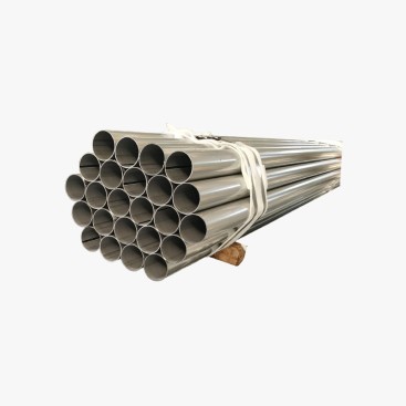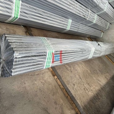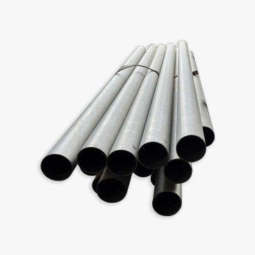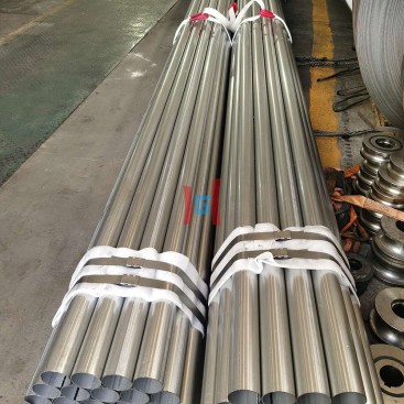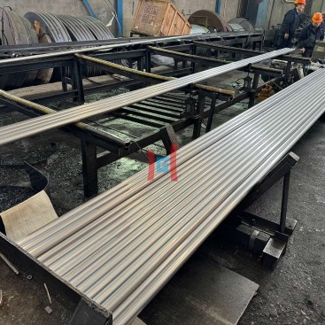
- Description
Description
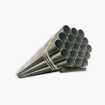
A 3 mm wall represents a shift from lightweight tubing toward applications that demand greater rigidity, resistance to local deformation, and a more substantial steel section. Compared with thin-wall alternatives, this thickness can be better suited to selected support frames, agricultural machinery, trailer components, furnace installations, and industrial conveying systems. However, wall thickness alone does not qualify a tube for structural or high-temperature service. Material grade, outside diameter, loading conditions, operating temperature, corrosion exposure, and fabrication quality remain decisive factors.
For aluminized steel pipe, selecting a 3 mm wall also changes the manufacturing and logistics equation. Welding may require different heat-input control and joint preparation, cutting and beveling can become more demanding, and the additional mass affects handling, transportation, and installation. In applications that depend on the protective aluminum-silicon coating, the coating condition around welds and heat-affected zones must be addressed during the fabrication plan.
1. What a 3 mm Wall Means for Tube Design
A 3 mm wall provides a larger steel cross-section than a thinner wall of the same outside diameter. This generally improves resistance to local denting and can increase section stiffness, making the tube worth evaluating for applications involving mechanical loads, support forces, vibration, or rough handling.
Structural Potential
The additional steel section can help resist local deformation and support loads when the tube geometry and material properties are appropriately selected.
Greater Fabrication Demand
Cutting, beveling, forming, and welding may require more time, suitable tooling, and revised process parameters.
Higher Installed Mass
The heavier tube affects lifting arrangements, support loads, shipping weight, and the amount of material that can be loaded per shipment.
Three millimetres should be treated as a design option rather than a universal structural threshold. A small-diameter tube with a 3 mm wall may have very different stiffness and buckling behavior from a large-diameter tube of the same thickness. Structural applications require checks for bending, compression, buckling, fatigue, joint strength, and the relevant design code.
2. Where Thin-Wall and 3 mm Tubes Diverge
Thin-wall tubing is commonly considered when reducing weight, controlling material consumption, or achieving efficient heat transfer is a priority. A 3 mm wall becomes more attractive when the application needs additional section capacity or greater tolerance of mechanical handling and local contact loads.
| Design Factor | Thin-Wall Tubing | 3 mm Wall Tubing |
|---|---|---|
| Primary objective | Weight reduction and material efficiency | Greater section thickness and resistance to local deformation |
| Typical evaluation | Exhaust components, ventilation, selected heat-transfer passages | Support frames, machinery components, selected furnace and conveying systems |
| Welding | Greater sensitivity to burn-through and localized overheating | Usually more material tolerance, but potentially higher heat demand and more preparation |
| Handling | Lower mass but potentially greater denting risk | Higher lifting and transportation loads |
| Main selection risk | Insufficient rigidity or limited wall allowance | Unnecessary weight, fabrication cost, or an unsuitable material for the service environment |
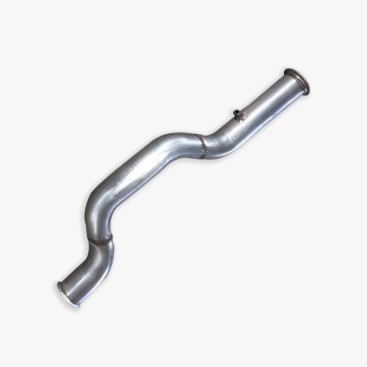
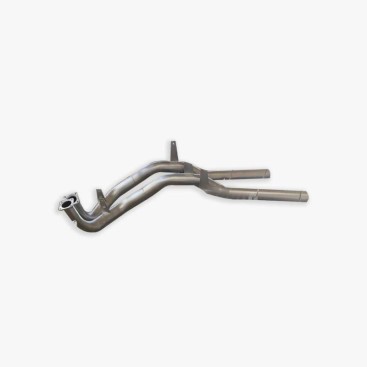
The application should determine the thickness, not the assumption that a thicker tube is always better. For exhaust systems, a thinner section may remain preferable where weight and thermal response dominate. For structural frames or equipment supports, a thicker section may be justified by calculated loads and connection requirements. Furnace and flue applications require separate assessment of temperature, oxidation, thermal expansion, and gas chemistry.
3. Weight Calculation and Transportation Impact
At a fixed outside diameter, increasing wall thickness increases the steel cross-sectional area and theoretical mass per metre. The increase is nonlinear because the internal diameter decreases as the wall becomes thicker. For long tubes, heavy bundles, and structural assemblies, this difference can materially affect lifting plans and shipment utilization.
Theoretical Steel Mass Formula
m = ρ × π × t × (D − t) × 10⁻⁶
Where m is steel mass per metre in kg/m, ρ is steel density in kg/m³, D is outside diameter in millimetres, and t is the steel substrate wall thickness in millimetres. Use approximately 7,850 kg/m³ as a preliminary density for ordinary steel, unless a different value is required for the specified material.
| Outside Diameter | Wall Thickness | Approx. Steel Mass per Metre |
|---|---|---|
| 50 mm | 1.2 mm | 1.44 kg/m |
| 50 mm | 2.5 mm | 2.92 kg/m |
| 50 mm | 3.0 mm | 3.48 kg/m |
| 76.1 mm | 3.0 mm | 5.39 kg/m |
Note: These are illustrative theoretical values for a steel density of 7,850 kg/m³. Coating mass, dimensional tolerances, weld geometry, packaging, and actual product weight are excluded.
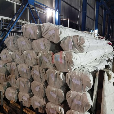
For a given outside diameter and length, a heavier tube increases the total shipment mass even when the number of pieces remains unchanged. Before confirming an order, calculate the estimated weight per piece, bundle, and shipment. Also verify lifting equipment capacity, storage supports, transport restrictions, and the payload limits of the intended container or vehicle.
Cost comparisons should use the same dimensional and coating basis. The material-cost component can be estimated from the calculated steel mass, but the final delivered cost may also include cutting, beveling, welding preparation, coating-related requirements, packaging, and freight. Request a supplier weight table or a dimension-based calculation when accurate loading plans are necessary.
4. Welding, Cutting, and Beveling Requirements
Welding Heat Input and Joint Preparation
A 3 mm wall generally provides more material than a thin-wall tube, reducing sensitivity to immediate burn-through under otherwise comparable welding conditions. However, the thicker section may require greater heat input or a different welding sequence to achieve the specified joint penetration. The correct settings depend on steel grade, joint geometry, welding process, position, and production speed.
Not every 3 mm tube requires a bevel or multiple welding passes. A square-edge joint may be appropriate for some qualified procedures, while other joint designs may need edge preparation to achieve the required penetration and weld profile. The decision should follow the applicable welding procedure and design requirements rather than wall thickness alone.
Cutting and Edge Preparation
Greater thickness can increase cutting time, tool wear, and the effort required to prepare consistent edges. If a bevel is specified, its angle, root face, root opening, and dimensional tolerances should be defined on the drawing or fabrication specification.
Inspect cut edges for excessive burrs, dross, notches, and local damage. These defects can complicate fit-up and may act as stress concentrators in fatigue-sensitive structures. For coated tubes, also identify whether cutting exposes the substrate and whether edge protection is required for the intended service environment.
Forming and Assembly
A thicker wall can improve resistance to local flattening, but it may require greater bending force and more robust tooling. Springback, bend radius, ovality, and dimensional fit still need to be verified. For fabricated frames, check hole locations, bracket clearances, end preparation, and the accessibility of welds before approving production.
5. Protecting the Coating Around Welds
Aluminum-silicon coating can provide oxidation protection for suitable steel products in elevated-temperature environments. Welding locally heats and changes the coated surface, so the coating around a joint may be altered or removed. With thicker sections, the heat distribution and cooling behavior can differ from those of thin-wall tubing, but the actual affected area depends on the welding method, heat input, joint design, and heat dissipation.
Coating Management Before and After Welding
- Define the weld zone: Identify joints, cut edges, and surfaces where coating disruption is expected.
- Control the process: Use a qualified welding procedure and avoid unnecessary heat input or excessive weld cleanup.
- Inspect the affected area: Check for exposed substrate, surface defects, and unacceptable coating separation.
- Agree on the final condition: Specify whether exposed areas are acceptable, require a compatible repair system, or must meet another documented protection requirement.
Coating repair should not be improvised. A repair material that performs well at ambient temperature may not be suitable for a hot furnace or exhaust environment. Where post-weld protection is required, confirm that the repair system is compatible with the base material, service temperature, atmosphere, and expected exposure.
For structural or high-temperature applications, assess the entire component rather than focusing exclusively on the coating. Weld strength, heat-affected-zone properties, oxidation resistance, thermal fatigue, and corrosion conditions may all determine service life.
6. Applications for 3 mm Wall Pipe
| Application | Selection and Inspection Priorities |
|---|---|
| Furnace tubes and high-temperature flues | Verify maximum metal temperature, gas chemistry, oxidation resistance, thermal expansion, support spacing, and material suitability. |
| Structural supports and frames | Check section capacity, buckling, joint strength, fatigue, connection details, and applicable structural standards. |
| Agricultural machinery and trailer frames | Evaluate impact, vibration, fatigue loading, corrosion exposure, weld quality, and mounting interfaces. |
| Industrial conveying pipes | Assess abrasion rate, conveyed material, flow velocity, impact, corrosion, and expected wall loss. |
| Equipment supports and rigid assemblies | Confirm deflection limits, installation loads, bracket geometry, weld access, and handling requirements. |
A 3 mm wall may be a candidate for conveying applications, but it does not automatically make a pipe abrasion-resistant. Abrasive wear depends on particle hardness, shape, impact angle, velocity, and material properties. Where severe wear is expected, calculate the required wear allowance or evaluate a purpose-designed wear-resistant material.
Similarly, aluminized coating suitability for furnace or flue service must be established using the actual temperature and atmosphere. Some environments may require a different alloy or protective system. A thicker carbon-steel substrate cannot compensate for a material that is chemically or thermally unsuitable for the application.
7. Procurement Checklist for Medium- and Heavy-Wall Tubing
Before issuing a purchase order, align the tube specification with the final application and fabrication plan. This is particularly important when the tube will be welded into a load-bearing assembly or installed in a high-temperature environment.
- Confirm material grade, product standard, delivery condition, and the definition of the nominal 3 mm wall.
- Specify outside diameter, length, dimensional tolerances, straightness, and ovality limits.
- Define the coating designation, coating acceptance criteria, and requirements for cut-edge or post-weld protection.
- State the intended operating temperature, atmosphere, loading, vibration, and corrosion conditions.
- Identify cutting, beveling, welding, forming, and inspection requirements.
- Request material certificates, batch traceability, and agreed inspection records.
- Calculate unit mass, bundle mass, total shipment weight, and lifting requirements.
- Confirm that connectors, clamps, brackets, and installation tools remain compatible with the specified tube.
For projects involving structural fabrication or hot-gas service, representative fabrication trials and documented inspection criteria can help establish whether the proposed material and manufacturing route are suitable. Final approval should be based on the relevant engineering calculations, qualified procedures, and applicable standards.
8. Teda Ganghua Supply Support
Teda Ganghua works with industrial procurement teams evaluating coated steel tubing for fabrication and equipment applications. Clear communication of wall thickness, tube dimensions, material grade, coating requirements, and downstream processing needs helps establish a consistent technical basis for supplier evaluation and order confirmation.
When discussing a 3 mm tube requirement, buyers should provide the outside diameter, required length, steel grade, coating designation, intended application, expected operating conditions, quantity, and relevant drawings. Teda Ganghua can review these requirements against the requested product specification and clarify the inspection and documentation expectations before order confirmation.
Explore aluminized steel tubes to review relevant product information and submit a technical inquiry. Suitability for structural loads, high-temperature service, or abrasive conveying should be confirmed against the approved design and service conditions rather than inferred from wall thickness alone.
Frequently Asked Questions
1. Is a 3 mm wall suitable for structural applications?
It can be suitable for selected structural components, but wall thickness alone does not establish load capacity. Engineers must verify the tube geometry, material grade, buckling resistance, joint strength, fatigue requirements, and applicable design standards.
2. Does a 3 mm tube always require beveling or multi-pass welding?
No. Joint preparation and pass count depend on the welding process, joint geometry, material, required penetration, and qualified welding procedure. Some joints can use square edges, while others require a bevel or additional passes.
3. Does a thicker wall improve high-temperature performance?
A thicker wall increases the steel section but does not automatically improve oxidation resistance or extend service life. Maximum metal temperature, atmosphere, thermal cycling, material grade, and coating suitability must all be evaluated.
4. Does welding damage the aluminized coating?
Welding changes the coating locally and may expose the substrate near the joint. The affected area depends on heat input and fabrication conditions. Inspection and any required post-weld protection should follow the agreed specification and service requirements.
5. What should be checked before replacing a thinner tube with a 3 mm wall?
Review mass per metre, inside diameter, flow area, connectors, clamps, brackets, weld preparation, tooling, support loads, and operating performance. The revised tube should be approved as an engineering change before it enters production.